
PROPELLER ENGINEERING
Wake: Why a Propeller Works in Uneven Water
The water dragged along by a moving hull never reaches the propeller at a uniform speed. Wake fractions by hull type, a Taylor wake factor table and the stern design mistakes that disturb the flow.
- PUBLISHED
- READING
- 5 min
- AUTHOR
- Eriş Pervane Mühendislik
When we size a propeller we usually start from the boat's speed. Yet the propeller never works in water moving at that speed. A moving hull drags part of the surrounding water along with it, so at the stern, right where the propeller turns, the water moves slower than the boat. This slowdown is called the wake, and it is often the first and most expensive detail left out of a propeller calculation.
How large can the wake be?
The thickness of the wake layer depends on the shape, length and speed of the hull. There are four typical cases:
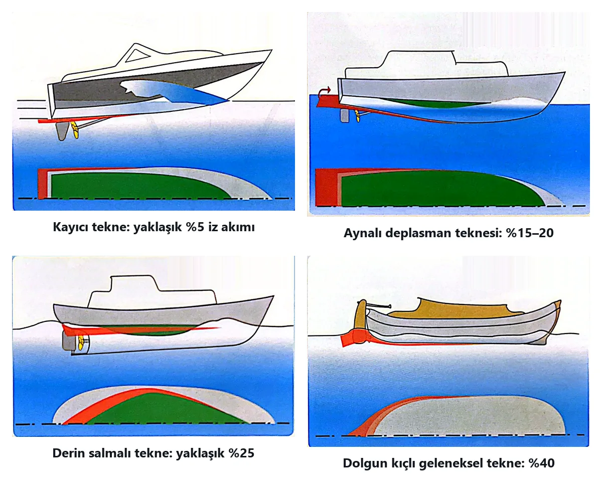
- Planing hull: the hull rides on the water, the dragged layer is thin and the wake is about 5%.
- Displacement hull with transom: the layer thickens towards the stern; the wake is around 15–20%.
- Deep-keel hull: with the propeller behind the keel the wake rises to about 25%.
- Traditional full stern: the propeller sits right behind a broad, full stern; the wake can reach 40%.
The percentage tells you how much of the ship speed is "lost". With a 40% wake the propeller works in water arriving at only about 60% of the boat speed.
The Taylor wake factor when there is no tank test
The most accurate wake value comes from towing-tank tests. Most boats never get one, so default values based on many tests and calculations are used instead:
| Vessel type | Single screw | Twin screw |
|---|---|---|
| Planing | 0.10 | 0.07 |
| Semi-planing | 0.15 | 0.11 |
| Displacement | 0.21 | 0.15 |
| Sailing yacht | 0.24 | 0.18 |
| Workboat | 0.27 | 0.20 |
| Tug | 0.30 | 0.22 |
| Inland vessel (barge) | 0.33 | 0.24 |
Twin-screw values are lower because the propellers turn away from the centreline in "cleaner" water. The table is a starting point only; hull fullness, section shape, draught, propeller type and the clearances around the propeller all change the real value.
Worked example
Take a single-screw displacement boat at 10 knots. With a wake factor of 0.21 the water reaches the propeller at roughly
10 × (1 − 0.21) = 7.9 knots
If the pitch were chosen for 10 knots, the propeller would load the engine more than expected. Allowing for the wake is the first step to the right pitch and diameter; you can try your own numbers in our propeller calculator.
The wake is not uniform across the propeller disc
The second effect matters even more. Different points of the propeller circle are at different distances from the hull. Near the hull the water is very slow, lower down it is faster, and each blade passes through these zones on every turn.
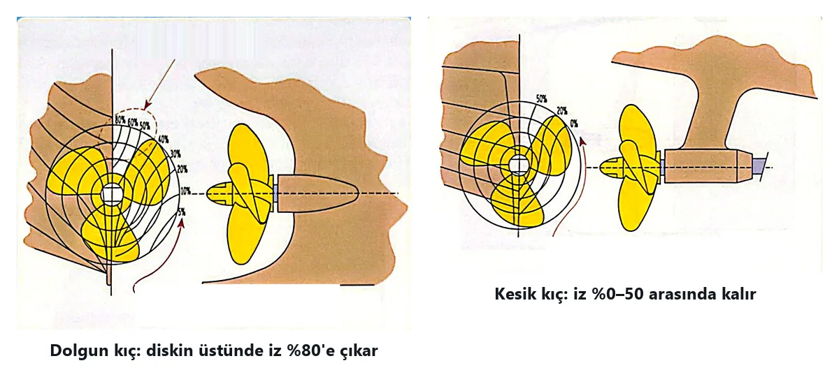
On a full stern the wake reaches 80% at the top of the disc and drops to 5% at the bottom. With a counter stern it stays between 0 and 50%. The blade load jumps as the blade passes the top and falls below. That fluctuation is a major source of vibration, noise and, at the top of the disc, cavitation.
Stern design mistakes that disturb the wake
- Propellers placed too close to the hull with hardly any clearance to the rudder.
- A skeg ending in a wide, flat vertical plate instead of a fair, tapered trailing edge.
- Cooling pipes and anodes placed right in front of or above the propeller.
- A steep shaft line. A large inclination creates a big "wake shadow" above and behind the shaft, so the blade roots get poor water and hub cavitation can follow.
If the angle between the shaft axis and the hull surface does not exceed 14° and the brackets are placed correctly, problems are rare.
Choosing the bracket
A single-arm P-bracket gives the best flow, which is why it is increasingly used on fast boats. If a V-bracket is used, its arms should not meet at a single point above the hub but join it tangentially. The angle between the arms must never be 120° for a 3-bladed, 90° for a 4-bladed or 72° for a 5-bladed propeller; at those angles two blades pass the arm wakes at the same moment and the pulses add up.
You cannot always make the wake smaller, but making it smoother is often enough for a quiet, efficient propeller.
If you are unsure whether your stern suits the propeller, contact us with your hull drawings.